



Perforated gypsum acoustic panel installation requires specialized mounting systems including acoustic studs, proper backing materials, perforation-preserving fasteners, and cavity insulation to maintain acoustic performance while ensuring structural integrity and optimal sound absorption.
Professional installation techniques preserve acoustic functionality while meeting structural requirements.
TRUSUS acoustic installation insight: perforated gypsum panel installation requires understanding acoustic principles, structural requirements, and specialized techniques to achieve optimal sound absorption performance.
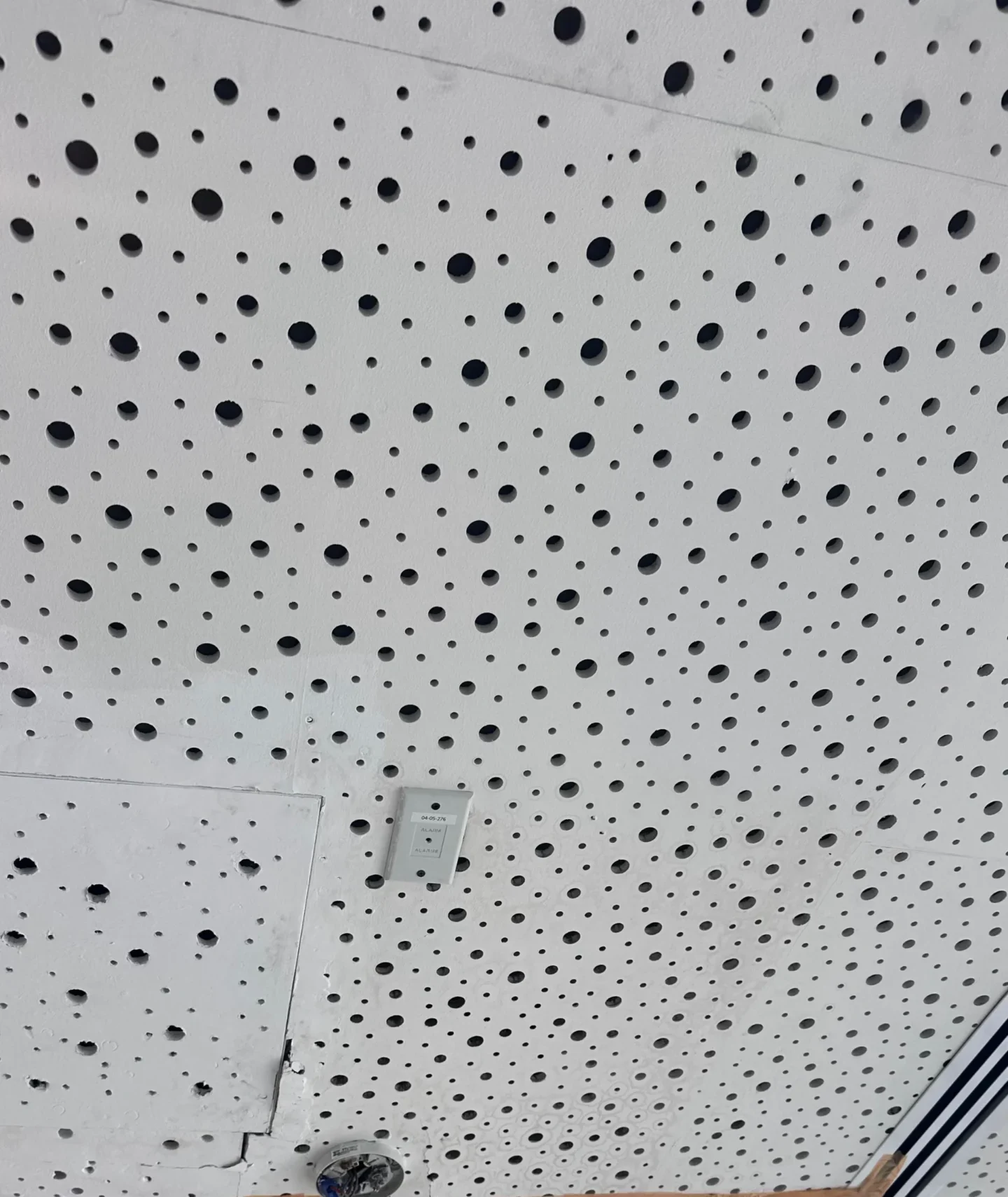
I increasingly see acoustic projects require precise installation techniques as building acoustic standards become more demanding and performance-critical.
Proper installation techniques ensure optimal acoustic performance while maintaining structural integrity and aesthetic quality.
Wall Installation Systems
| Installation Component | Function | Specification | Acoustic Impact |
|---|---|---|---|
| Acoustic studs | Framework support | 70-100mm depth | Minimizes sound bridging |
| Backing insulation | Sound absorption | 50-75mm mineral wool | Enhances absorption coefficient |
| Perimeter sealing | Air gap control | Acoustic sealant | Prevents sound leakage |
| Fastener spacing | Panel attachment | 300mm centers | Maintains panel integrity |
Wall installation requires systematic approach to preserve acoustic functionality.
Ceiling Installation Requirements
| Ceiling Component | Structural Function | Acoustic Function | Installation Method |
|---|---|---|---|
| Primary suspension | Load distribution | Vibration isolation | Resilient hangers |
| Secondary grid | Panel support | Acoustic decoupling | Non-rigid connections |
| Panel mounting | Secure attachment | Perforation protection | Specialized clips |
| Cavity treatment | Performance enhancement | Sound absorption | Insulation installation |
Ceiling installation demands enhanced structural and acoustic considerations.
Acoustic Cavity Design
| Cavity Element | Dimension | Material | Performance Benefit |
|---|---|---|---|
| Air space depth | 50-100mm | Air cavity | Resonance tuning |
| Absorption material | 25-50mm thickness | Mineral fiber | Sound energy conversion |
| Backing surface | Solid or perforated | Varies by design | Reflection control |
| Cavity sealing | Complete perimeter | Acoustic barriers | Prevents air leakage |
Properly designed cavities maximize acoustic panel effectiveness.
Fastening Systems
| Fastener Type | Application | Panel Protection | Acoustic Consideration |
|---|---|---|---|
| Acoustic screws | Direct attachment | Countersunk heads | Avoid perforation damage |
| Clip systems | Concealed mounting | No visible fasteners | Maintain acoustic surface |
| Adhesive systems | Specialized bonding | Full surface contact | Enhanced performance |
| Mechanical anchors | Heavy-duty applications | Structural connection | Load distribution |
Specialized fastening preserves acoustic surface integrity and performance.
Installation Process Sequence
| Installation Stage | Key Activities | Quality Control | Performance Impact |
|---|---|---|---|
| Framework preparation | Stud/grid installation | Alignment verification | Structural adequacy |
| Cavity preparation | Insulation installation | Coverage completeness | Absorption optimization |
| Panel positioning | Accurate placement | Perforation orientation | Acoustic functionality |
| Final finishing | Sealing and trimming | Air gap elimination | Performance integrity |
Systematic installation ensures optimal acoustic and structural performance.
Special Considerations
| Consideration Area | Requirement | Implementation | Performance Impact |
|---|---|---|---|
| Perforation orientation | Holes face sound source | Correct panel direction | Maximum absorption |
| Joint treatment | Acoustic continuity | Specialized sealants | Prevents sound leakage |
| Electrical integration | Service coordination | Pre-planning required | Maintains acoustic integrity |
| Maintenance access | Future serviceability | Removable panels | Long-term performance |
Special considerations ensure long-term acoustic performance and functionality.
Common Installation Errors
| Error Type | Impact | Prevention | Correction Method |
|---|---|---|---|
| Rigid mounting | Reduced performance | Resilient connections | Modify mounting system |
| Inadequate sealing | Sound leakage | Complete air sealing | Retrofit sealing |
| Wrong orientation | Poor absorption | Proper panel direction | Reinstall correctly |
| Damaged perforations | Performance loss | Careful handling | Panel replacement |
Avoiding installation errors ensures optimal acoustic system performance.
Why Installation Precision Matters
| Standard Installation | Precision Acoustic Installation |
|---|---|
| Basic attachment methods | Specialized acoustic techniques |
| Generic mounting systems | Performance-optimized mounting |
| Standard finishing practices | Acoustic-specific procedures |
Precision installation techniques ensure optimal acoustic performance and system reliability.
The Industry Shift Behind Installation Questions
| Traditional Panel Installation | Modern Acoustic Installation |
|---|---|
| Decorative panel mounting | Performance-critical installation |
| Standard construction methods | Specialized acoustic techniques |
| Basic attachment systems | Engineered mounting solutions |
I increasingly see acoustic projects implement specialized installation techniques that optimize sound absorption performance through precise mounting, cavity design, and acoustic system integration.
What Does NRC Mean For Perforated Gypsum Acoustic Panels?
NRC (Noise Reduction Coefficient) represents the average sound absorption performance of perforated gypsum panels across four key frequencies (250, 500, 1000, 2000 Hz), with values typically ranging 0.70-0.95 for quality acoustic panels, indicating excellent sound absorption capabilities.
NRC provides standardized measurement for comparing acoustic panel absorption performance across different products and applications.
TRUSUS NRC insight: NRC values enable scientific comparison of acoustic panel performance, with higher values indicating superior sound absorption for improving interior acoustic environments.
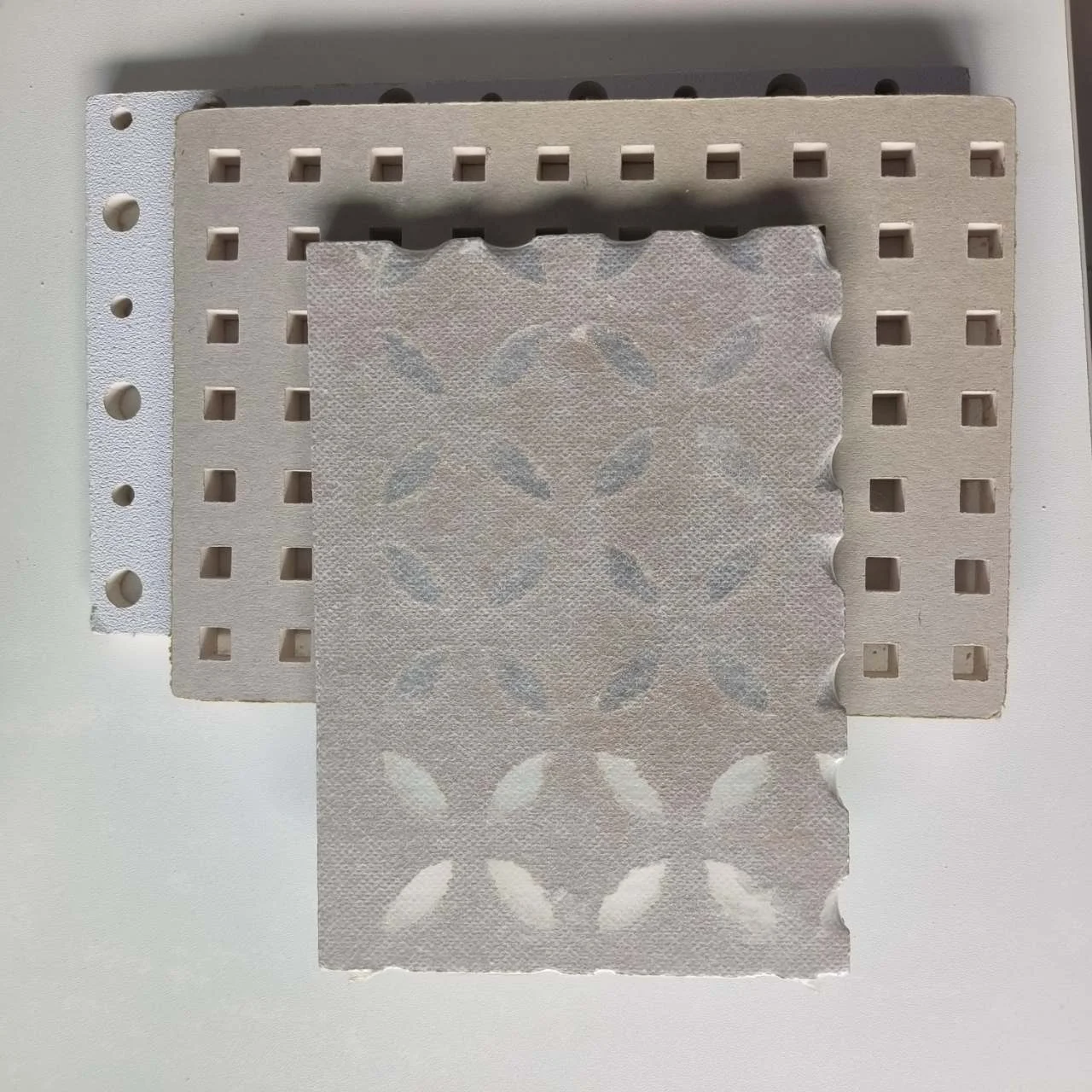
I increasingly see acoustic specifications require precise NRC values as building acoustic standards become more performance-oriented and measurable.
Understanding NRC enables informed selection of acoustic panels for specific sound absorption requirements and performance objectives.
NRC Calculation Method
| Frequency | Absorption Coefficient | Typical Range | Calculation Weight |
|---|---|---|---|
| 250 Hz | Low frequency absorption | 0.60-0.85 | 25% of NRC |
| 500 Hz | Mid-low frequency | 0.70-0.95 | 25% of NRC |
| 1000 Hz | Mid-high frequency | 0.75-1.00 | 25% of NRC |
| 2000 Hz | High frequency absorption | 0.70-0.90 | 25% of NRC |
NRC represents arithmetic average of absorption coefficients across four standard frequencies.
Performance Classification
| NRC Range | Performance Level | Application Suitability | Acoustic Benefit |
|---|---|---|---|
| 0.90-1.00 | Excellent | Critical acoustic spaces | Maximum absorption |
| 0.80-0.89 | Very good | Professional environments | High absorption |
| 0.70-0.79 | Good | General commercial use | Significant absorption |
| 0.60-0.69 | Moderate | Basic acoustic treatment | Moderate absorption |
Higher NRC values indicate superior sound absorption performance for acoustic control.
Frequency-Specific Analysis
| Acoustic Problem | Dominant Frequency | Required Coefficient | NRC Consideration |
|---|---|---|---|
| Speech clarity | 500-2000 Hz | >0.70 at speech range | High overall NRC |
| Music acoustics | 250-4000 Hz | Balanced absorption | Consistent across range |
| Noise control | Broad spectrum | >0.80 overall | High NRC essential |
| Echo reduction | 1000-2000 Hz | Peak absorption | Mid-high frequency focus |
Different acoustic challenges require specific frequency response characteristics beyond overall NRC.
Testing Standards
| Test Standard | Method | Measurement Conditions | Industry Acceptance |
|---|---|---|---|
| ASTM C423 | Reverberation room | Laboratory conditions | North American standard |
| ISO 354 | Sabine method | Standardized setup | International standard |
| ASTM E795 | Impedance tube | Small sample testing | Material characterization |
| Field testing | In-situ measurement | Actual installation | Performance verification |
Standardized testing ensures reliable and comparable NRC measurements.
Installation Impact On NRC
| Installation Factor | NRC Impact | Optimization Method | Performance Result |
|---|---|---|---|
| Cavity depth | Significant effect | 50-100mm optimal | Enhanced low frequencies |
| Backing material | Moderate impact | Absorptive backing | Improved overall NRC |
| Edge sealing | Performance critical | Complete air sealing | Maintains rated performance |
| Mounting method | Variable effect | Proper techniques | Achieves laboratory NRC |
Installation quality directly affects realized NRC performance in actual applications.
NRC Limitations
| Limitation Area | Impact | Consideration | Design Response |
|---|---|---|---|
| Single number rating | Oversimplified | Frequency-specific needs | Detailed coefficient analysis |
| Laboratory conditions | Idealized performance | Real-world variations | Field verification |
| Standard frequencies | Limited range | Extended frequency needs | Specialized testing |
| Installation variations | Performance differences | Quality control | Proper installation |
Understanding NRC limitations enables better acoustic design and performance prediction.
Application Selection Guide
| Space Type | Required NRC | Performance Priority | Panel Selection |
|---|---|---|---|
| Recording studios | >0.90 | Maximum absorption | Premium acoustic panels |
| Conference rooms | 0.80-0.90 | Speech clarity | High-performance panels |
| Offices | 0.70-0.85 | Noise control | Commercial grade panels |
| Lobbies | 0.60-0.80 | Echo reduction | General acoustic panels |
Different applications require specific NRC performance levels for optimal acoustic environments.
Why NRC Understanding Matters
| Generic Acoustic Selection | NRC-Based Selection |
|---|---|
| Appearance-focused choices | Performance-driven decisions |
| Unquantified expectations | Measurable acoustic goals |
| Variable performance results | Predictable acoustic outcomes |
Understanding NRC enables scientific acoustic panel selection for specific performance requirements.
The Industry Shift Behind NRC Questions
| Traditional Acoustic Materials | Modern Performance-Based Selection |
|---|---|
| Subjective acoustic judgments | Quantified performance metrics |
| Generic acoustic treatments | NRC-optimized solutions |
| Appearance-priority selection | Performance-priority specification |
I increasingly see acoustic projects implement NRC-based selection criteria that ensure measurable sound absorption performance for specific acoustic environment requirements.
How To Attach Perforated Gypsum Acoustic Panels To A Ceiling?
Perforated gypsum acoustic panels attach to ceilings using suspended grid systems with specialized acoustic clips, resilient hangers, and proper cavity design to maintain structural integrity while preserving acoustic performance through proper installation techniques.
Ceiling attachment requires specialized mounting systems designed for acoustic panel performance and structural safety.
TRUSUS ceiling attachment insight: acoustic panel ceiling installation demands specialized suspension systems that provide structural support while maintaining acoustic isolation and performance integrity.

I increasingly see ceiling acoustic installations require engineered mounting systems as acoustic performance standards and safety requirements become more stringent.
Professional ceiling attachment ensures structural safety while maintaining optimal acoustic panel performance.
Suspension System Components
| System Component | Function | Specification | Performance Benefit |
|---|---|---|---|
| Primary hangers | Main support | 1200-1500mm spacing | Structural load distribution |
| Main runners | Grid framework | Heavy-duty profiles | System stability |
| Cross tees | Panel support | Acoustic-rated sections | Direct panel mounting |
| Perimeter angles | Edge support | Wall connection | Complete system integrity |
Engineered suspension systems provide reliable support for acoustic panel installations.
Acoustic Clip Systems
| Clip Type | Attachment Method | Panel Support | Acoustic Benefit |
|---|---|---|---|
| Spring clips | Resilient mounting | Secure retention | Vibration isolation |
| Mechanical clips | Positive engagement | Reliable hold | Easy maintenance access |
| Magnetic systems | Non-penetrating | Clean attachment | Perforation protection |
| Adhesive clips | Bonded connection | Permanent mount | Seamless appearance |
Specialized clips ensure secure panel attachment while preserving acoustic functionality.
Grid System Design
| Grid Element | Spacing | Load Capacity | Installation Method |
|---|---|---|---|
| Main runners | 1200mm centers | 15-25 kg/m | Hanger suspension |
| Cross tees | 600mm centers | 10-15 kg/m² | Interlocking connection |
| Border conditions | Perimeter support | Variable loads | Adjustable mounting |
| Splice connections | Grid continuity | Transfer loads | Mechanical joints |
Properly designed grid systems distribute loads while maintaining acoustic performance.
Panel Mounting Methods
| Mounting Method | Application | Advantages | Limitations |
|---|---|---|---|
| Lay-in system | Standard grid | Easy access | Visible grid |
| Concealed grid | Clean appearance | Hidden structure | Complex installation |
| Direct attachment | Structural deck | Minimal thickness | Limited access |
| Clip-in system | Specialized grid | Secure retention | System-specific |
Different mounting methods suit various aesthetic and performance requirements.
Structural Considerations
| Structural Factor | Design Requirement | Safety Consideration | Performance Impact |
|---|---|---|---|
| Dead load | Panel + grid weight | Structural adequacy | Deflection limits |
| Live load | Maintenance access | Code requirements | System stability |
| Seismic forces | Lateral restraint | Safety compliance | Connection integrity |
| Thermal movement | Expansion joints | Stress relief | Long-term performance |
Structural design ensures safe and durable acoustic panel installations.
Cavity Design Integration
| Cavity Element | Function | Installation Method | Acoustic Benefit |
|---|---|---|---|
| Insulation placement | Sound absorption | Above panel installation | Enhanced performance |
| Air space depth | Resonance tuning | Grid height adjustment | Frequency optimization |
| Backing treatment | Reflection control | Structural coordination | Absorption enhancement |
| Plenum coordination | Service integration | Planned installation | System compatibility |
Integrated cavity design maximizes acoustic panel effectiveness in ceiling applications.
Installation Process
| Installation Stage | Key Activities | Quality Control | Performance Verification |
|---|---|---|---|
| Grid installation | Framework erection | Level and alignment | Structural integrity |
| Service coordination | MEP integration | Clearance verification | System compatibility |
| Panel placement | Acoustic installation | Proper orientation | Performance confirmation |
| System commissioning | Final adjustments | Performance testing | Acoustic verification |
Systematic installation ensures optimal acoustic and structural performance.
Maintenance Accessibility
| Access Method | Panel Removal | Service Access | Replacement Ease |
|---|---|---|---|
| Lift-out panels | Simple removal | Complete access | Easy replacement |
| Hinged panels | Swing access | Partial access | Specialized hardware |
| Removable sections | Section removal | Targeted access | Modular replacement |
| Permanent installation | No access | Limited service | Reconstruction required |
Maintenance access planning ensures long-term system serviceability and performance.
Why Specialized Attachment Matters
| Standard Ceiling Installation | Acoustic Panel Attachment |
|---|---|
| Basic grid suspension | Engineered acoustic systems |
| Generic mounting methods | Performance-optimized attachment |
| Standard support systems | Specialized acoustic hardware |
Specialized attachment systems ensure acoustic panel performance while meeting structural requirements.
The Industry Shift Behind Ceiling Questions
| Traditional Ceiling Systems | Modern Acoustic Ceiling Installation |
|---|---|
| Generic suspended ceilings | Performance-engineered systems |
| Basic grid installations | Acoustic-optimized mounting |
| Standard attachment methods | Specialized acoustic hardware |
I increasingly see ceiling acoustic projects implement engineered mounting systems that optimize structural support, acoustic performance, and long-term serviceability for professional acoustic environments.
What Is The Difference Between NRC And STC?
NRC (Noise Reduction Coefficient) measures sound absorption performance within a space for controlling reverberation and echo, while STC (Sound Transmission Class) measures sound isolation between spaces for blocking noise transmission, representing fundamentally different acoustic performance characteristics.
NRC and STC address different acoustic problems requiring different material properties and design approaches.
TRUSUS acoustic rating insight: NRC and STC serve different acoustic functions - NRC improves sound quality within spaces while STC prevents sound transfer between spaces, requiring distinct material selection and design strategies.
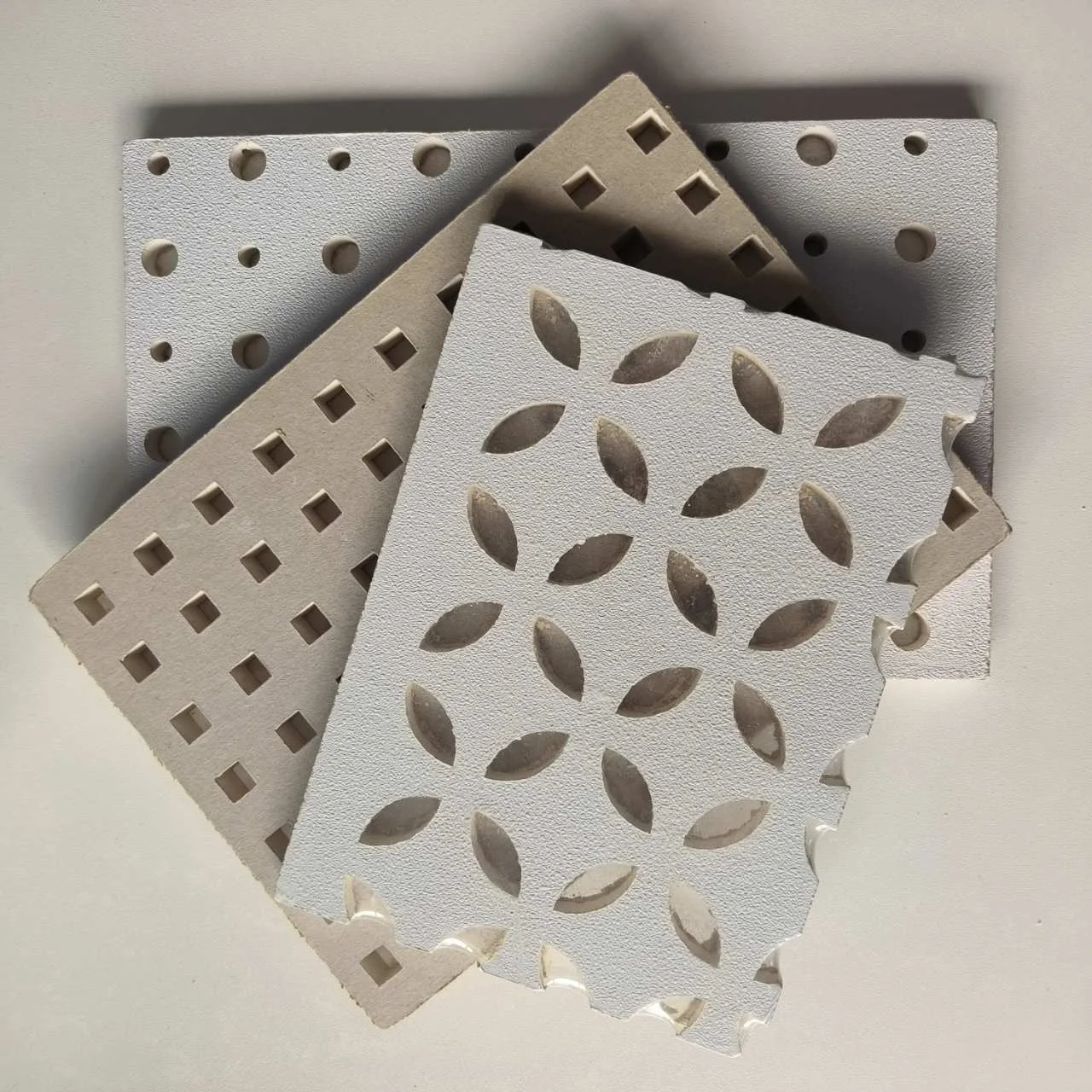
I increasingly see acoustic projects require clear understanding of NRC and STC differences as acoustic specifications become more precise and performance-critical.
Understanding rating differences enables proper material selection and acoustic design for specific sound control objectives.
Fundamental Measurement Differences
| Measurement Aspect | NRC | STC | Application Focus |
|---|---|---|---|
| Performance measured | Sound absorption | Sound transmission loss | Different acoustic problems |
| Test method | Reverberation room | Transmission loss suite | Distinct testing environments |
| Frequency range | 250-2000 Hz average | 125-4000 Hz weighted | Different frequency emphasis |
| Value range | 0.00-1.00+ | 25-65+ typical | Different scales |
NRC and STC measure completely different acoustic phenomena requiring different evaluation methods.
Acoustic Problem Solutions
| Acoustic Problem | Primary Solution | Rating Priority | Material Selection |
|---|---|---|---|
| Room echo/reverberation | Sound absorption | High NRC | Absorptive materials |
| Noise from adjacent spaces | Sound blocking | High STC | Mass/isolation systems |
| Speech intelligibility | Absorption + isolation | Both NRC and STC | Balanced approach |
| Privacy control | Sound blocking | STC priority | Transmission loss focus |
Different acoustic problems require prioritizing either NRC or STC performance characteristics.
Material Performance Comparison
| Material Type | Typical NRC | Typical STC | Performance Characteristics |
|---|---|---|---|
| Perforated gypsum panels | 0.70-0.95 | 25-35 | High absorption, low isolation |
| Standard gypsum wall | 0.05-0.10 | 35-45 | Low absorption, moderate isolation |
| Insulated wall assembly | 0.10-0.15 | 45-55 | Low absorption, high isolation |
| Acoustic foam | 0.80-1.00 | 15-25 | Very high absorption, minimal isolation |
Materials typically excel in either absorption or transmission loss, rarely both simultaneously.
Application Selection Guide
| Space Function | NRC Priority | STC Priority | Design Strategy |
|---|---|---|---|
| Recording studios | Very high | Very high | Dual-performance systems |
| Conference rooms | High | Moderate | Absorption focus with isolation |
| Open offices | High | Low-moderate | Absorption emphasis |
| Residential bedrooms | Moderate | High | Isolation priority |
Different spaces require emphasizing NRC or STC based on acoustic objectives.
System Design Implications
| Design Approach | NRC Optimization | STC Optimization | Implementation Method |
|---|---|---|---|
| Surface treatments | Add absorptive materials | Increase mass/isolation | Different material strategies |
| Wall/ceiling design | Cavity absorption | Multiple layers/decoupling | Distinct construction methods |
| Space planning | Acoustic zoning | Sound isolation barriers | Different layout priorities |
| Material selection | Porous/fibrous materials | Dense/sealed assemblies | Opposite material characteristics |
Optimizing for NRC versus STC requires fundamentally different design strategies and materials.
Testing And Standards
| Rating System | Test Standard | Measurement Method | Industry Application |
|---|---|---|---|
| NRC | ASTM C423/ISO 354 | Reverberation time | Material specification |
| STC | ASTM E90/ISO 140 | Transmission loss | Assembly rating |
| Combined testing | Multiple standards | Separate evaluations | Comprehensive performance |
| Field testing | ASTM E1041/E336 | In-situ measurement | Installation verification |
Different standards and testing methods verify NRC and STC performance independently.
Common Selection Errors
| Selection Error | Problem | Correct Approach | Performance Result |
|---|---|---|---|
| Using NRC for isolation | Inadequate sound blocking | Select for STC | Proper noise control |
| Using STC for reverberation | Poor room acoustics | Select for NRC | Better sound quality |
| Single-rating focus | Incomplete solution | Consider both ratings | Comprehensive acoustic design |
| Generic acoustic materials | Suboptimal performance | Application-specific selection | Optimal acoustic results |
Understanding rating applications prevents acoustic design errors and performance failures.
Why Rating Understanding Matters
| Single-Rating Approach | Comprehensive Rating Understanding |
|---|---|
| Incomplete acoustic solutions | Targeted performance optimization |
| Mismatched material selection | Application-appropriate choices |
| Suboptimal acoustic results | Effective acoustic control |
Understanding NRC and STC differences enables proper acoustic design and material selection.
The Industry Shift Behind Rating Questions
| Traditional Acoustic Approach | Modern Performance-Based Design |
|---|---|
| Generic acoustic treatments | Rating-specific solutions |
| Subjective acoustic judgments | Quantified performance targets |
| Single-function materials | Multi-performance optimization |
I increasingly see acoustic projects implement comprehensive rating analysis that selects materials and systems based on specific NRC and STC requirements for targeted acoustic performance objectives.
Conclusion
At TRUSUS, I see perforated gypsum acoustic panel applications evolving from basic installation toward comprehensive acoustic performance optimization requiring specialized mounting techniques, NRC performance understanding, engineered ceiling systems, and proper rating selection.
Success requires treating acoustic panels as engineered building systems demanding systematic analysis of installation methods, performance metrics, structural requirements, and acoustic objectives for optimal sound environment control.